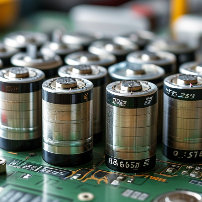
| Battery Cell | Standard 18650 lithium-ion cell | Nominal voltage: 3.6–3.7 V
Full-charge voltage: 4.20 V
Typical capacity: 2,000–3,500 mAh | Use cells with the same chemistry, model, age, capacity range, and state of charge in one pack. | Confirm the manufacturer datasheet, allowable charge voltage, discharge cutoff, and continuous-current rating. |
| Battery Cell | High-energy cell | Typical capacity: 3,000–3,600 mAh
Typical continuous discharge: approximately 5–10 A | Suitable for applications that prioritize runtime over high power, such as moderate-current electronics. | Do not use high-energy cells for loads that exceed their tested continuous-current rating. |
| Battery Cell | High-power cell | Typical capacity: 1,500–2,500 mAh
Typical continuous discharge: approximately 10–30 A | Use for power tools, mobility equipment, and other high-current applications when the exact cell rating supports the load. | Continuous and pulse-current ratings are different; use the continuous rating for system design. |
| Battery Cell | Cell dimensions | Nominal diameter: 18 mm
Nominal length: 65 mm
Common tolerance: approximately ±0.5 mm | Allow extra space for holders, insulation, weld tabs, heat-shrink tubing, and mechanical compression. | Protected 18650 cells can be approximately 68–71 mm long and may not fit standard holders. |
| Battery Cell | Cell matching | Recommended capacity spread: no more than 2–3% within a parallel group
Recommended voltage spread before assembly: about 0.02 V or less | Measure capacity, internal resistance, and resting voltage before combining cells. | Never combine unknown, swollen, damaged, corroded, or visibly inconsistent cells. |
| Pack Configuration | Series connection | Pack nominal voltage = 3.6–3.7 V × number of series groups
Pack full voltage = 4.20 V × number of series groups | A 4S pack is approximately 14.4–14.8 V nominal and 16.8 V when fully charged. | The protection board must match the exact number of series groups. |
| Pack Configuration | Parallel connection | Pack capacity = cell capacity × number of parallel cells
Current capability increases approximately with parallel count | A 3P group made from 3,000 mAh cells is approximately 9,000 mAh nominal. | Current sharing depends on cell matching, interconnect resistance, weld quality, and temperature. |
| Protection Board | Overcharge protection | Typical threshold: approximately 4.20–4.30 V per cell group | Choose a board designed for the cell chemistry and series count. | Protection thresholds vary by board; verify the data sheet instead of relying only on advertised nominal voltage. |
| Protection Board | Over-discharge protection | Typical threshold: approximately 2.5–3.0 V per cell group | Use a cutoff that is compatible with the cell datasheet and the required usable capacity. | Repeated deep discharge can reduce capacity and increase safety risk. |
| Protection Board | Overcurrent and short-circuit protection | Common design range: approximately 5–40 A, depending on board type | Select a continuous-current rating above the maximum operating current, with margin for startup surges. | Board ratings are affected by temperature, copper thickness, MOSFET resistance, airflow, and wiring. |
| Protection Board | Balancing function | Passive balancing commonly begins near the upper-charge region; balancing current is often tens of milliamps | Use a balancing board for multi-series packs when cell-group voltage drift is expected. | Balancing is not a substitute for matched cells or a correctly designed charger. |
| Protection Board | Temperature monitoring | Common sensor: NTC thermistor
Typical nominal resistance: 10 kΩ at 25°C | Place the sensor where it can detect the warmest cell group or the main current path. | Confirm the board's compatible sensor curve and charge/discharge temperature limits. |
| Charger | Constant-current/constant-voltage charging | For standard lithium-ion cells: 4.20 V per series group at full charge | Use a charger designed for the exact series count and pack chemistry. | Do not charge lithium-ion packs with lead-acid, nickel-based, or unregulated power supplies. |
| Connectors | Power connector selection | Choose a connector with a continuous-current rating above the maximum load; a 20–30% design margin is advisable. | Use locking connectors for vibration-prone equipment and keyed connectors where reverse polarity is possible. | Connector ratings depend on contact temperature, wire size, duty cycle, and mating quality. |
| Connectors | Balance connector | One balance connection is typically required for each series junction plus the pack negative terminal. | For an S-series pack, use an S-series-compatible balance lead and matching charger or service instrument. | Incorrect balance-wire order can permanently damage the protection board or charger. |
| Interconnects | Cell connection strip | Common material: pure nickel or nickel-plated steel
Typical pure-nickel thickness: approximately 0.10–0.20 mm | Use pure nickel for lower resistance and higher-current paths when the welding process is suitable. | Confirm material with a resistance or magnet test; magnetic response alone is not a complete identification method. |
| Interconnects | Busbars and main conductors | Use copper or appropriately sized copper-based conductors for high-current paths. | Size conductors for continuous current, acceptable voltage drop, temperature rise, and fault current. | Do not depend on thin nickel strip alone for high-current main output paths. |
| Insulation | Positive-terminal insulating ring | Common material: fish paper or high-temperature insulating polymer | Install an insulating ring on every cell positive terminal before arranging cells or applying compression. | The ring must remain flat, centered, and resistant to the expected temperature range. |
| Insulation | Cell wrapping | Common material: PVC or polyolefin heat-shrink tubing | Replace damaged cell sleeves before assembly and cover exposed metal after welding. | A damaged sleeve can allow the cell casing to short against nickel strip or a neighboring cell. |
| Mechanical Design | Cell holders and spacers | Common materials: flame-retardant plastic or high-temperature polymer | Use spacers that prevent cell-to-cell abrasion and maintain consistent alignment. | Avoid sharp edges, excessive compression, and designs that trap heat around the cells. |
| Mechanical Design | Pack enclosure | Common materials: polycarbonate, ABS, aluminum, or other application-suitable enclosure materials | Provide strain relief, ventilation where appropriate, insulation, and protection from impact and moisture. | Metal enclosures require reliable electrical insulation between the cells, busbars, and enclosure. |
| Thermal Management | Operating temperature | Typical lithium-ion guidance: charge only above 0°C unless the cell specifically permits low-temperature charging; discharge limits vary by cell. | Keep the pack within the cell manufacturer's specified temperature range. | Measure cell temperature during the highest-load and highest-charge conditions. |
| Testing | Final pack inspection | Check polarity, series-group voltage, insulation resistance, connector wiring, and protection response. | Test the pack with a current-limited supply or approved charger before applying the full load. | Stop immediately if the pack becomes hot, swells, emits odor, or shows unexpected voltage imbalance. |
| Safety | Assembly method | Use a resistance welder designed for cylindrical lithium-ion cells rather than direct soldering to cell terminals. | Minimize heat transferred to the cell and inspect every weld for secure mechanical attachment. | Never puncture, crush, short-circuit, overcharge, or mix cells with different specifications. |